1. Causes of ring artifacts
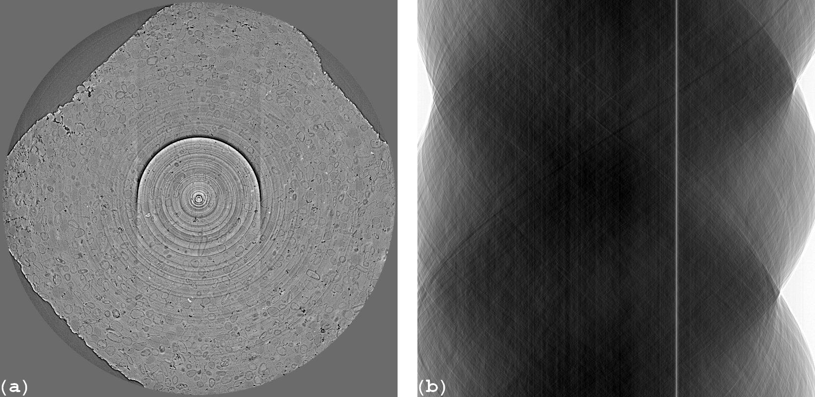
Figure 1. (a) Reconstructed image. (b) Sinogram.
Ring artifacts in a reconstructed image (Fig. 1a), corresponding to stripe artifacts in the sinogram (Fig. 1b), come from two major sources:
Irregular responses of a detecting system.
Uncorrelated pixels between images with sample (projections) and images without sample (flat-field or white-field images).
1.1. Irregular responses of a detecting system
Irregular responses of a detecting system are caused by defects in different parts of the system such as the non-linear response of a sensor chip, dust on optics components (lens, mirrors…), and especially a scintillator, which is the major contributor. As can be seen in Fig. 2, defects from a scintillator are clearly visible.
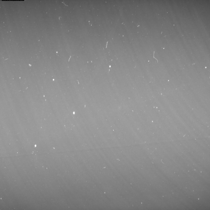
Figure 2. Flat-field image shows defects of a scintillator
However, there are invisible defects which also result in stripe artifacts but can only be revealed by analysing the linear response of a detector. Analysis can be performed by acquiring projections through an X-ray absorber (e.g a glass plate) at different thicknesses by rotating the plate in the range of 0 degree to ~80 degree (to make sure that the plate doesn’t block X-ray completely). Lines were fitted to the measured intensities of every pixel based on the Beer-Lambert’s law. Intercepts and slopes of the fitting results of all pixels (Fig. 3) help to reveal the underlying information about the quality of the scintillator.
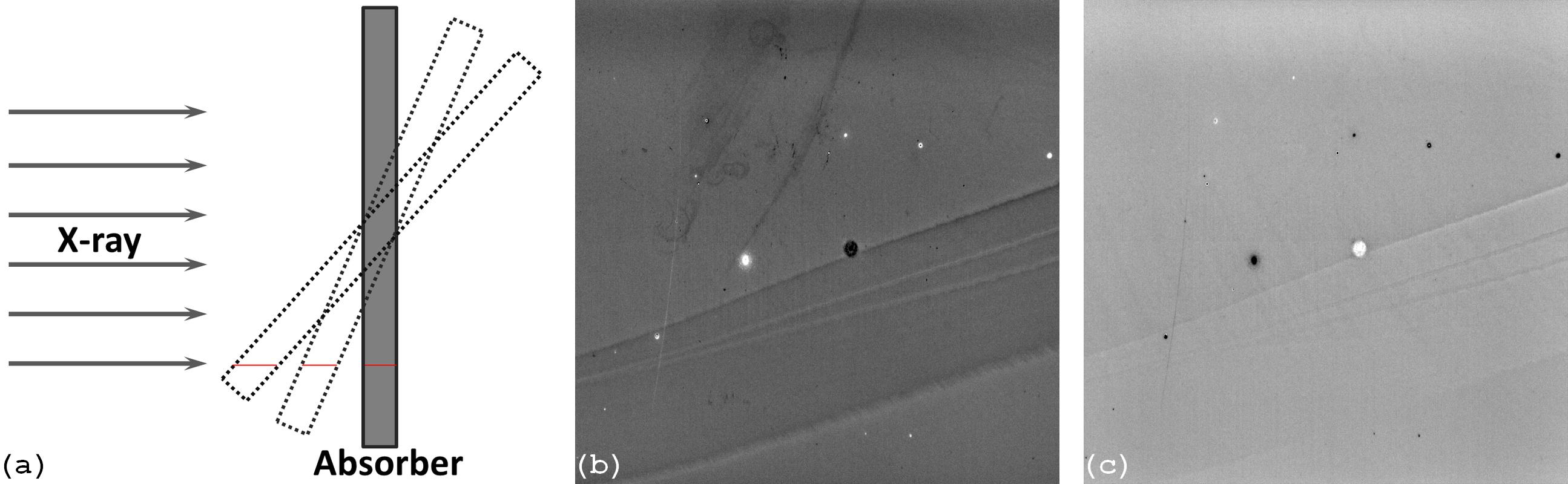
Figure 3. Analysis of the linear response of the detector, giving the image in Fig. 2, helps to reveal underlying defects. (a) X-ray intensities are varied by rotating an X-ray attenuator. (b) Intercepts of the fitting results. (c) Slopes of the fitting results.
Retrieved response maps are useful to characterize detector systems and can be used to correct irregular responses of large size detectors where the response of each pixel is independent. However, in synchrotron-based micro-tomography systems, where scintillators are mainly unstructured types to achieve high resolution, this cannot be done due to the scattering of scintillation photons (Fig. 4) making the response of each pixel depend on its neighbors.

Figure 4. Demonstration of the scattering of scintillation photons in a scintillator-coupled X-ray detector by taking a flat-field image with a half field of view blocked. (a) Under 0.05s of exposure time. (b) Under 0.5s of exposure time.
As a result, the shape and absorption characteristics of a sample dictate the influence of scattered light to the response of a pixel. This means that the occurrence of artifacts depend on samples and projection angles. Figure 6 shows reconstructed images at the same slice of three samples with different shapes and absorption characteristics (Fig. 5) where all tomographic datasets were collected under the same conditions. As can be seen, there are ring artifacts in sample 3 which don’t occur in sample 1 and 2.
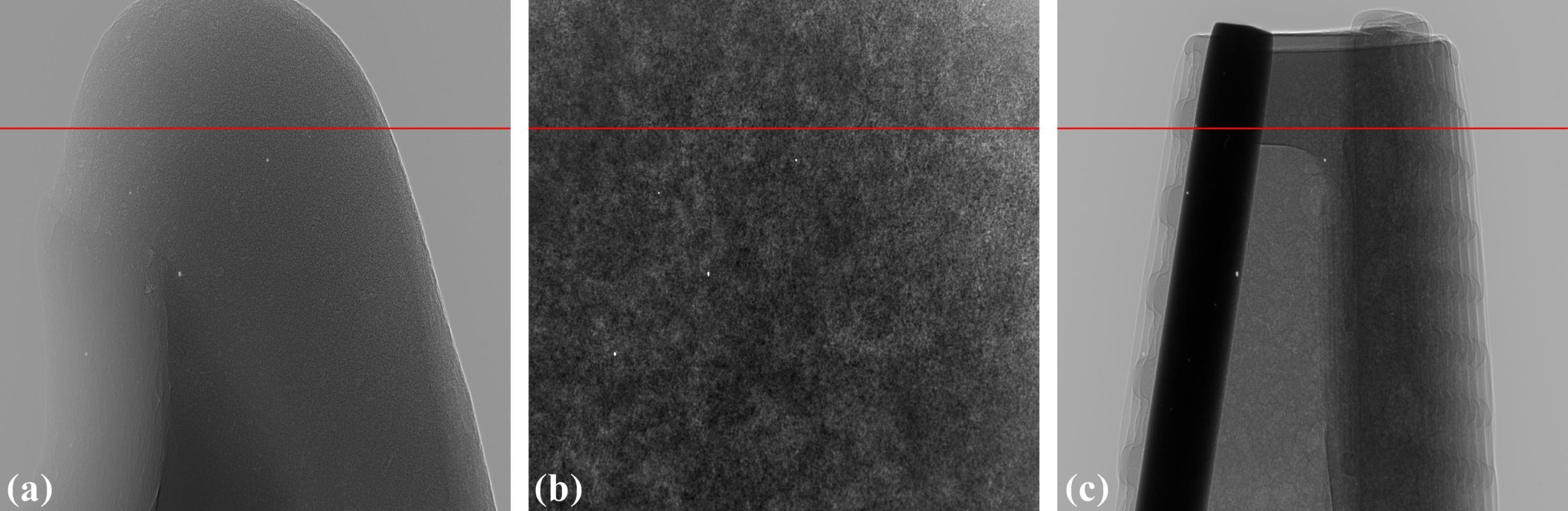
Figure 5. Flat-field-corrected projections from three different types of samples. (a) Sample 1 giving a low dynamic range of transmitted intensities. (b) Sample 2 giving a medium dynamic range of transmitted intensities. (c) Sample 3 giving a high dynamic range of transmitted intensities.
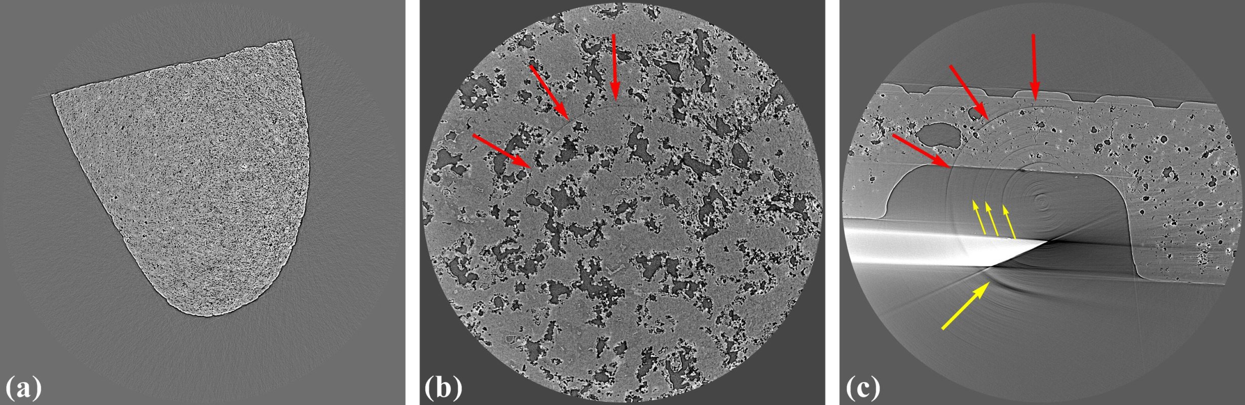
Figure 6. Occurrence of ring artifacts is sample-dependent as can be seen in the reconstructed images of three samples at the same detector row. (a) Sample 1. (b) Sample 2. (c) Sample 3.
1.2. Mismatched pixels in flat-field image
The second source of ring artifacts comes from the flat-field correction process based on the Beer-Lambert’s law
\[\frac{I}{I_0} = \int_{}e^{-\alpha (x,y,z) dx}\]in practice, it is done using the following formula
\[\frac{P_{\theta}-D}{F-D}\]where \(P_{\theta}\) is a projection image of a sample at a rotation angle of \(\theta\), \(D\) is a dark-field image taken with a photon source off, and \(F\) is a flat-field image taken without the sample. This process is applied to all projections and it is here that fixed features in a flat-field image which are uncorrelated to projection images give rise to stripe artifacts in sinograms or ring artifacts in reconstructed images. Figure 7 shows two types of fixed features which can be found in flat-field images. The first one is zingers caused by scattered x-rays hitting the CCD chip directly (Fig. 7(a)). The second one is blobs (Fig. 7(b)) introduced by X-ray optics components in a synchrotron-based tomography system. These blobs can be shifted during data acquisition process due to the heat load resulting in uncorrelated pixels between projections and the flat-field image.
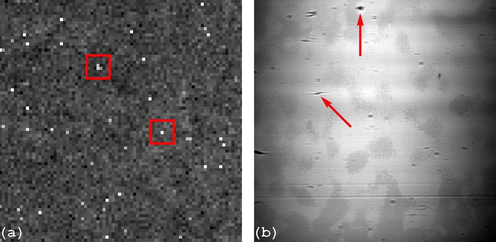
Figure 7. Examples of some fixed features can be found in the flat-field images. (a) Zingers. (b) Blobs come from X-ray optics components.