3. Methods for removing ring artifacts
3.1. Preprocessing methods
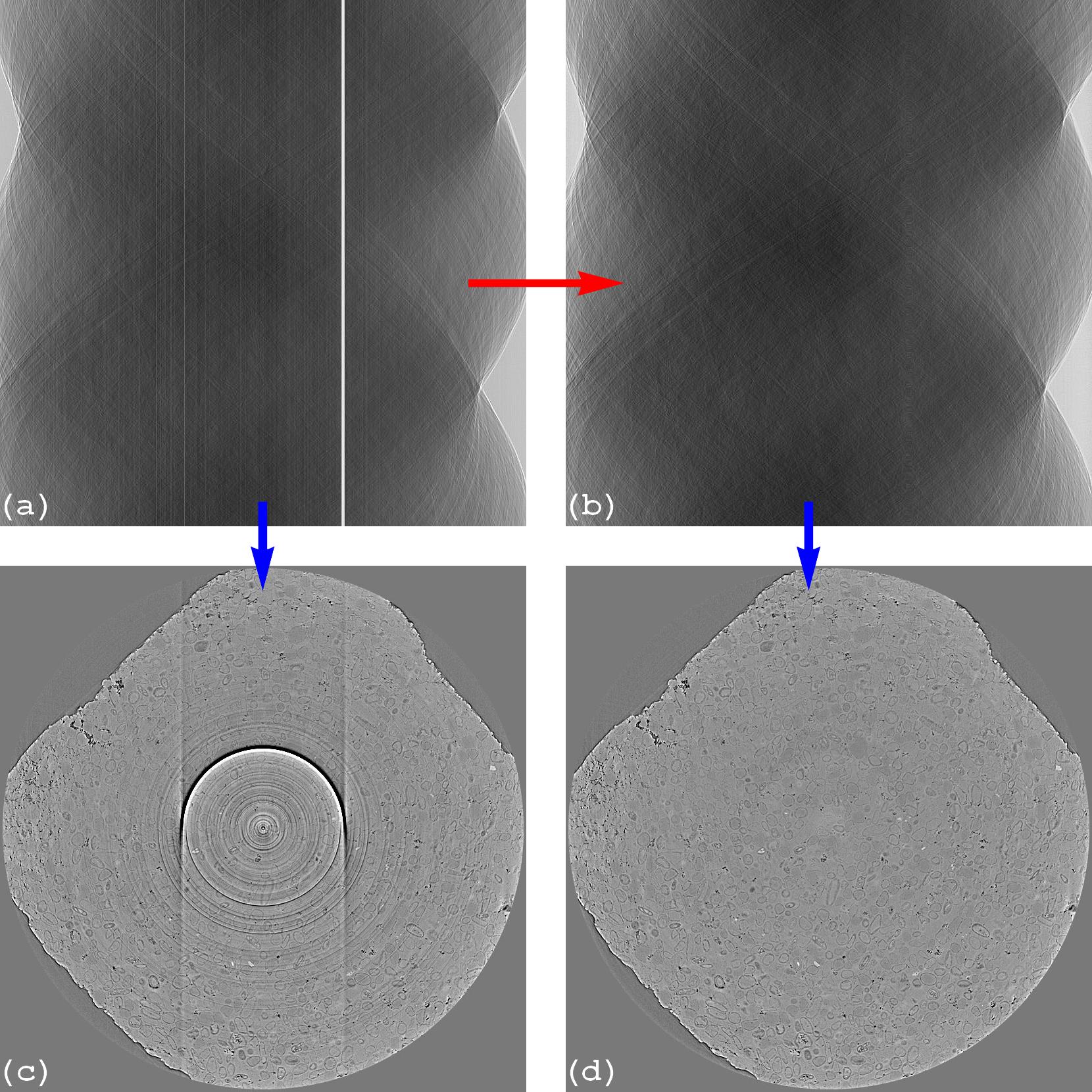
Figure 1. Preprocessing methods work on sinogram space . (a) Sinogram before correction. (b) Sinogram after correction. (c) Reconstructed image from sinogram (a). (d) Reconstructed image from sinogram (b).
Lots of methods for removing ring artifacts in the sinogram space, where the artifacts appear as straight lines or stripe artifacts, were proposed. They use all sorts of image processing methods: smoothing filter, segmentation, interpolation… It is easier to classify these methods based on assumptions about causes of artifacts they rely on. There are 4 basic assumptions:
Stripe artifacts are caused by differences in offsets of intensities between neighboring pixels (i.e the full stripe type). Most of methods rely on this assumption. They use different ways of calculating these offsets and mainly use the average of intensities along the angular direction of a sinogram to detect stripes. This assumption is valid for a detector system where the response of each pixel is quite independent, e.g in a large area detector used for a cone-beam lab-based tomography system.
Stripe artifacts are corresponding to high-frequency components in the Fourier domain. As a result, they can be removed by damping these components. Methods relying on this assumption risk to introduce extra artifacts due to side effects of damping other high-frequency features.
Stripe artifacts are caused by mismatches between a flat-field image and projection images.
Stripe artifacts are caused by differences in responses (to incomming photons) between neighboring pixels. These methods are the main part of this documentation.
We will analyse implementations of the methods relied on the assumption 1, 2, and 4 in details to understand the pros and cons of each method, to know how to use them efficiently and how to improve them. Because there are many methods for removing stripe artifacts and each of them works best on certain types of stripes, to find the best combination of methods users need to assess: the quality of a flat-field image; sizes of artifacts; the dynamic range of intensities; and intensity profiles of pixels inside stripes in comparison to their neighbors.
- 3.1.1. Equalization-based methods for removing partial and full stripe artifacts
- 3.1.2. Prior methods for removing stripe artifacts
- 3.1.3. Method for locating stripe artifacts
- 3.1.4. Method for removing large stripes
- 3.1.5. Method for removing unresponsive and fluctuating stripes
- 3.1.6. Combinations of methods
3.2. Postprocessing methods
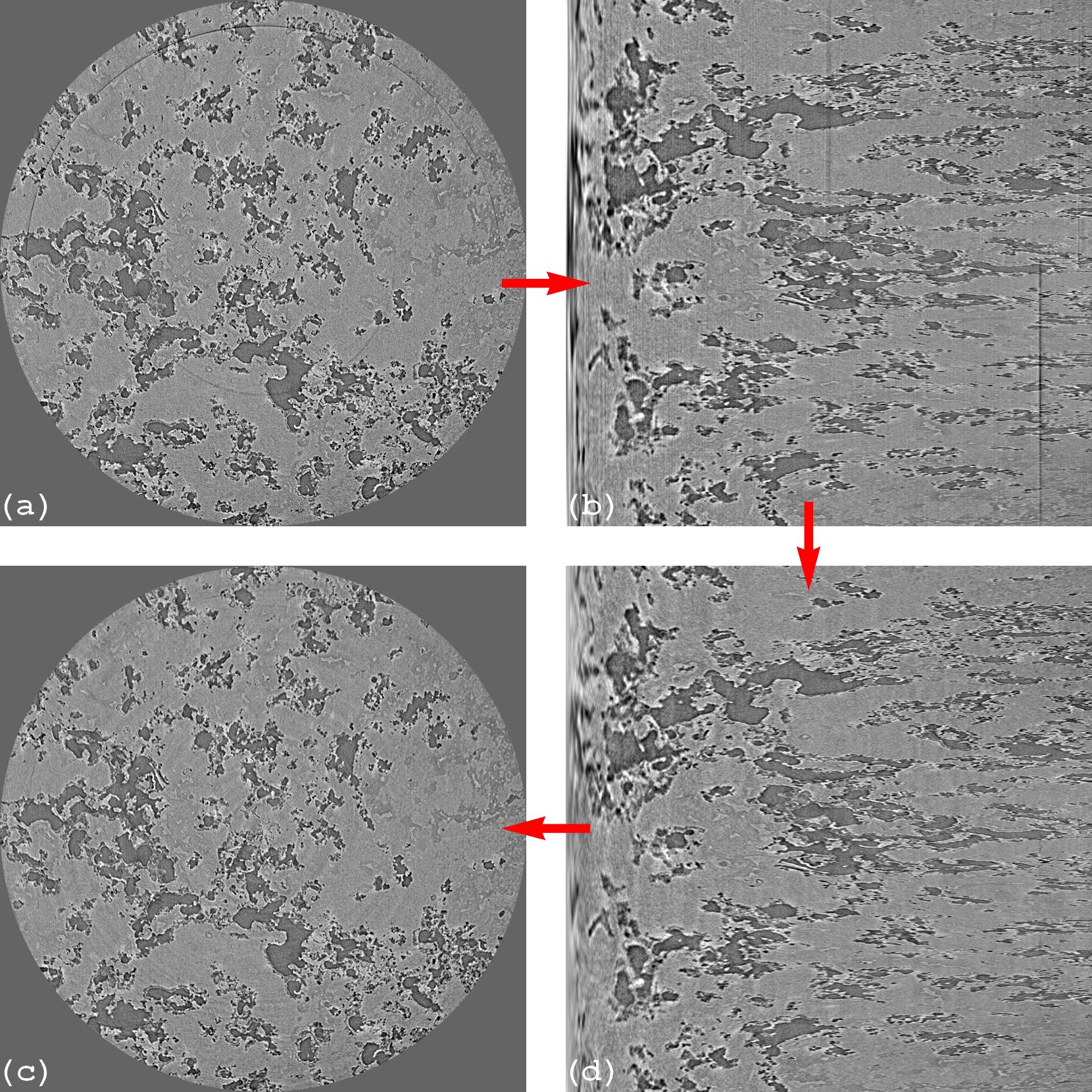
Figure 2. Postprocessing methods work on the reconstruction space . (a) Reconstructed image before correction. (b) Polar transformation of image (a). (d) Stripe artifacts removed from image (b). (c) Cartesian transformation of image (d).
These methods work on the reconstruction space by transforming the problem of removing ring artifacts to the problem of removing stripe artifacts using the polar transformation (Fig. 2). It is important to know that the assumptions of 1 and 4 above, used by pre-processing methods to remove stripe artifacts, are not applicable to a transformed image. These assumptions are based on the underlying physics of a detecting system and the standard way of acquiring tomographic data which are no more valid in the reconstruction space. Postprocessing methods are popularly used in cone-beam tomography for a few reasons:
Due to the cone-beam geometry, reconstructing a slice requires a few adjacent sinograms (i.e multiple-rows of projection images). This means that pre-processing methods may need to be adapted to work on a 3D image. This is not convenient and can be computationally expensive.
To reduce the cone-beam artifacts, tomographic data are often acquired using a full rotation (360-degree) scan. This results full ring artifacts instead of haft ring artifacts with residual streak artifacts as in a 180-degree scan (Fig. 1(c)). This goes well with the polar transformation.
Commercial cone-beam systems often go with their own reconstruction software which may only output reconstructed images to end-users.
There are limitations of postprocessing methods which users need to be aware of: they can’t remove side effects of unresponsive and fluctuating stripe artifacts (section 2) which not only give rise to ring artifacts but also streak artifacts in a reconstructed image (Fig. 1(c)); they can yield void-center artifacts caused by over-smoothing the over-sampled areas of the transformed image (left sides of Fig. 2(b,d)); there is information loss and artifact propagation during the transformation between the polar and Cartesian coordinate systems.
3.3. Common side effects of ring artifact removal methods
Methods relying on the assumptions 1 and 2 in section 3.1 often introduce two side-effect artifacts: extra ring artifacts (Fig. 3(b)) and void-center artifacts (Fig. 3(c)). Void-center artifacts are introduced by over-adjusted parameters. Extra ring artifacts are introduced by the false detection of stripes or by damping high-frequency components which are not corresponding to stripe artifacts. These side effects are often observed in X-ray synchrotron-based micro-tomography where there is the edge-enhancement effect caused by a coherent X-ray source. This effect increases the high-frequency components of an image which affects the performance of the mentioned methods.
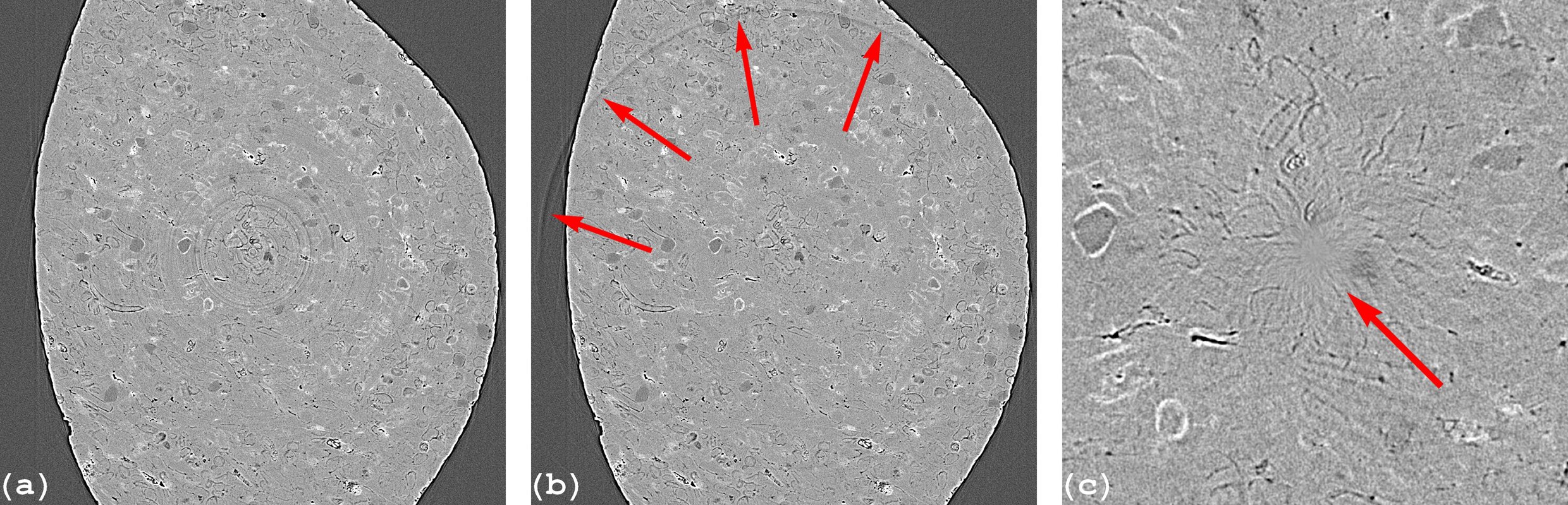
Figure 3. Side effects of ring removal methods relying on the assumptions 1 and 2 in section 3.1. (a) Reconstructed image without ring removal. (b) Extra ring artifacts. (c) Void-center artifacts.