2. Classification of stripe artifact types
Occurrence of stripe artifacts (ring artifacts in reconstructed images) depending on a sample makes it difficult to find a generic approach for removing them. Furthermore, there are many types of stripe artifacts which may require different ways of treatment. The use of pre-processing techniques such as distortion correction or phase retrieval blurs and enlarges these stripes, making it even more challenging to clean them. It is important to understand physical causes of stripe artifacts and classify them. This helps to tackle the problem most efficiently. By comparing the intensity profile, which is the plot of measured intensities against angles, of a defective pixel with its adjacent non-defective pixel we can classify stripe artifacts into four different types.
2.1. Full stripe
A typical profile of a full stripe exhibits intensities that are offset at all angles compared with that of a neighboring good pixel (Fig. 1(a, b)). It gives rise to a half-ring artifact (in 180-degree scanning tomography) in the reconstructed image (Fig. 1(c)).
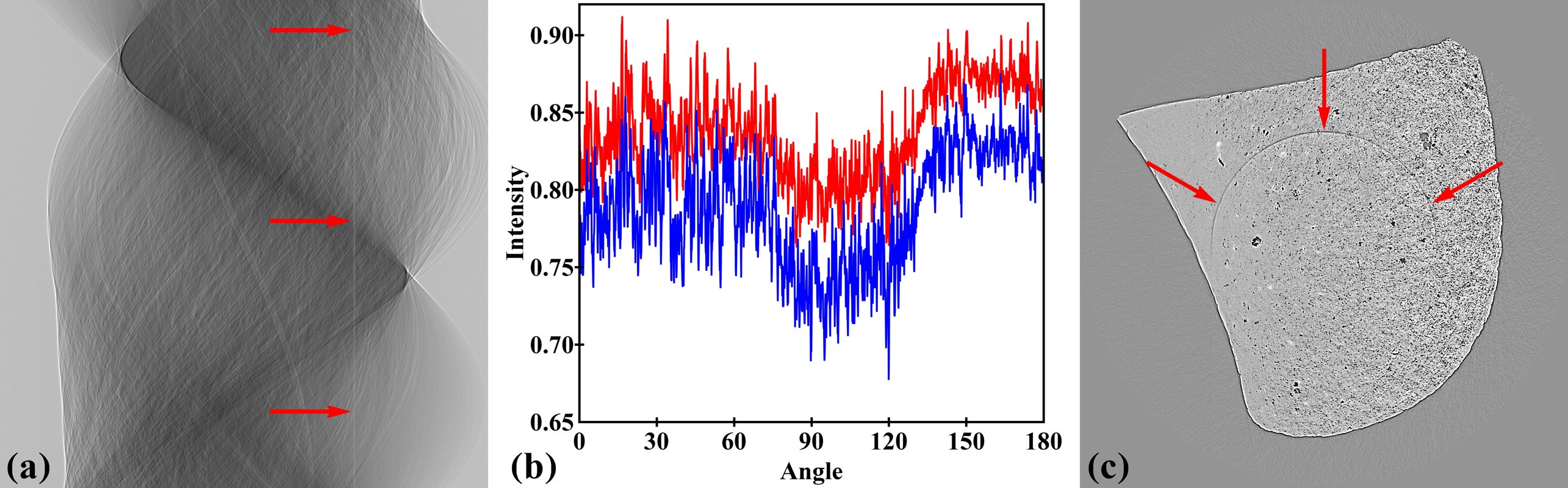
Figure 1. Demonstration of the full stripe artifact. (a) Stripe in a sinogram (arrowed). (b) Intensity profile along the stripe (red color) in comparison with an adjacent good pixel (blue color). (c) Ring artifact in the reconstructed image.
2.2. Partial stripe
Different to a full stripe, intensities of a partial stripe are offset only at certain ranges of angles as demonstrated in Fig. 2. As a result, it gives rise to a partial ring artifact in the reconstructed image (Fig. 2(c)).
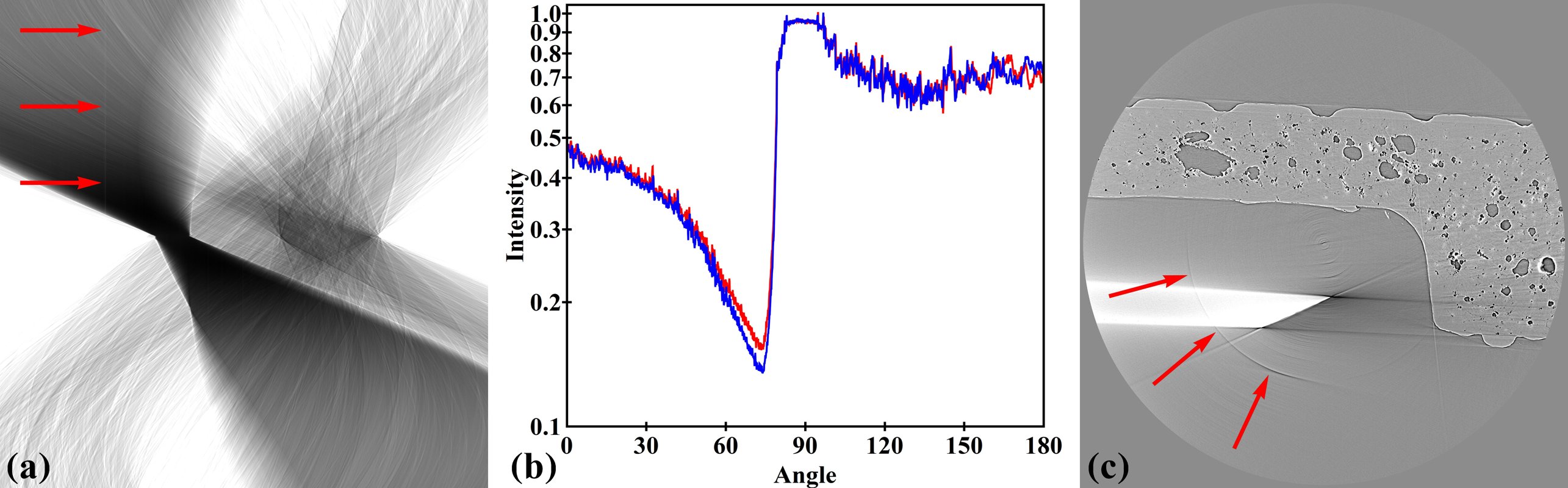
Figure 2. Demonstration of a partial stripe artifact. (a) Partial stripe in a sinogram (arrowed). (b) Intensity profile along the stripe (red color) in comparison with an adjacent good pixel (blue color). (c) Partial ring artifact in the reconstructed image.
2.3. Unresponsive stripe
Intensities of this type of stripe are independent of angles. A pixel is not responsive to the variation of intensity versus angles as the same way as its neighboring good pixel. This type of stripes may come from dead pixels of a sensor chip, light-blocking dusts or damaged scintillator (bright blobs in Fig. 3(a)) giving rise to stripes of constant brightness as clearly visible in Fig. 3(b). Missing information in these stripes strongly affects the reconstructed image; the constant intensity results in a prominent half-ring, and high-frequency edges of the stripes cause severe streak artifacts (Fig. 3(c)).
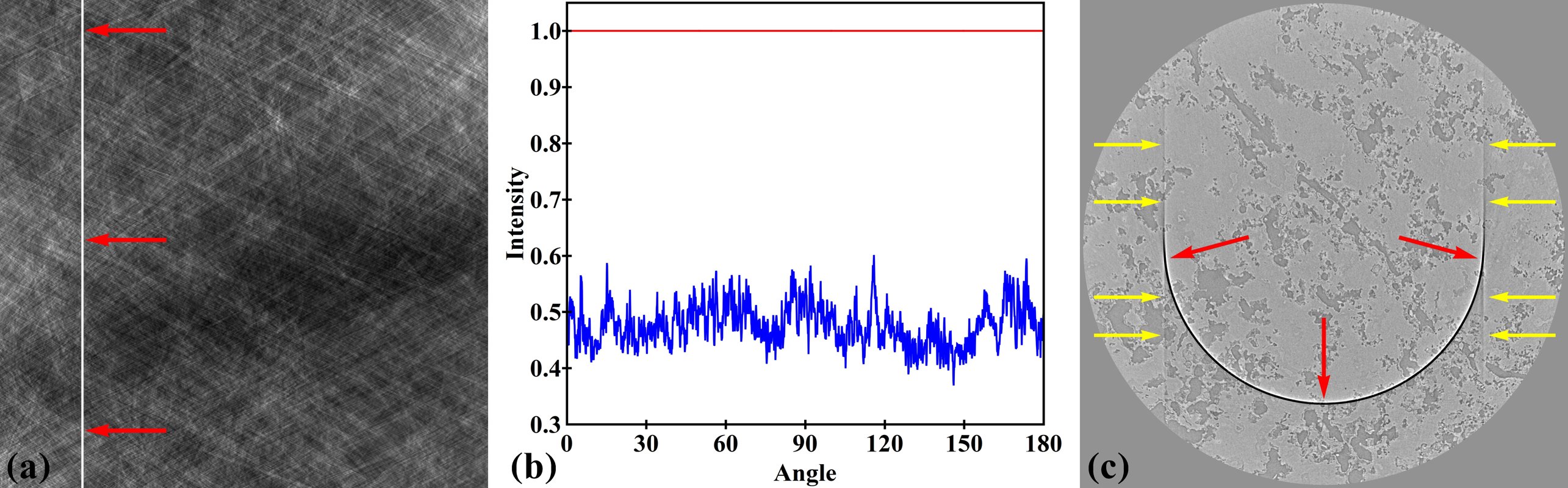
Figure 3. Demonstration of an unresponsive stripe artifact. (a) Unresponsive stripe in a sinogram (red arrows). (b) Intensity profile along the stripe (red color) in comparison with an adjacent good pixel (blue color). (c) Ring artifact (red arrows) and streak artifacts (yellow arrows) in the reconstructed image.
2.4. Fluctuating stripe
Intensities inside this type of stripe fluctuate significantly across angles. The stripe may be caused by defective pixels of a sensor chip rather than optical components. They are extremely small in number and their size is often between 1 or 2 pixels. Like unresponsive stripes, they give rise to both ring artifacts and streak artifacts as demonstrated in Fig. 4.
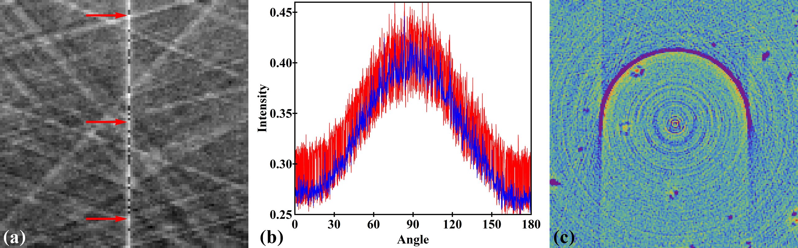
Figure 4. Demonstration of a fluctuating stripe artifact. (a) Fluctuating stripe in a sinogram (zoomed in and arrowed). (b) Intensity profile along the stripe (red color) in comparison with an adjacent good pixel (blue color). (c) Ring artifact and streak artifacts in the reconstructed image.
2.5. Other types of stripes
There are other types of stripes which are combinations of above stripes or the extension of them such as large stripes (Fig. 5) or blurry stripes. Blurry stripes may come from the use of pre-processing methods such as phase retrieval or distortion correction. Large stripes are caused by large defects in a detector which are not always visible in radiographs. They may come from adjacent areas of a damaged scintillator which receives extra scattering light, i.e. the so-called halo effect, as shown in Fig. 5. Large stripes may need a separate treatment to reduce side effects of cleaning methods.
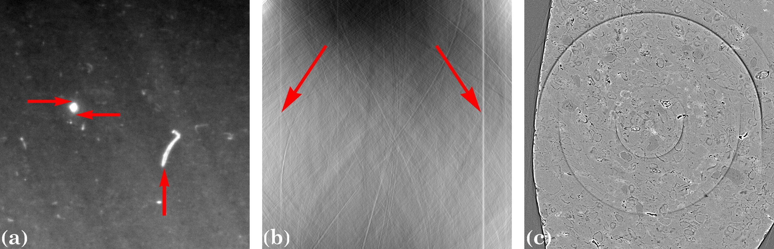
Figure 5. Causes and impact of large stripes. (a) Large defects (vertical arrow) and the areas around the over-exposed blob (horizontal arrows) cause large stripes. (b) Large stripes in the sinogram (arrowed). (c) Large ring artifacts in the reconstructed image.
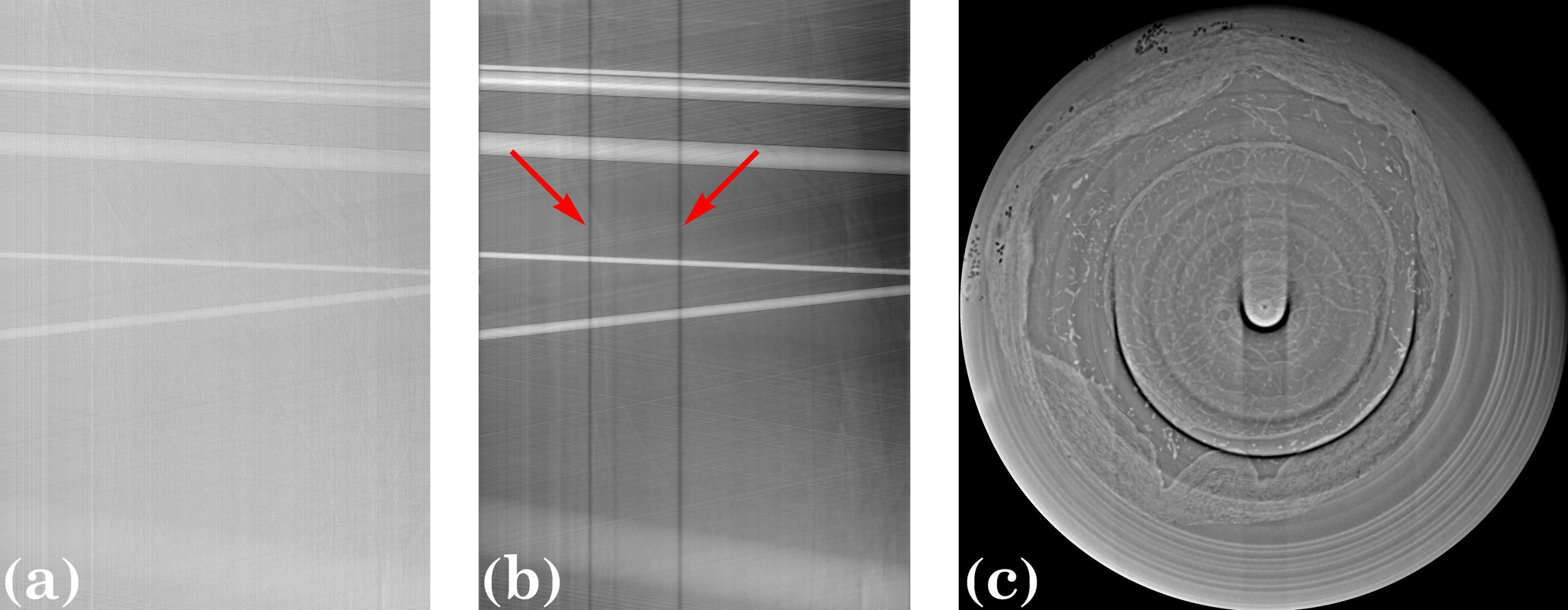
Figure 6. Demonstration of blurry stripes caused by applying a low-pass filter to 2D projections. (a) and (b) are sinograms at the same row of a detector before and after the low-pass filter is applied. (c) Blurry ring artifacts in the reconstructed image.